Engineering Details
The Core-loc® shape is shown in the following figures:
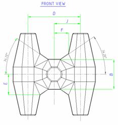
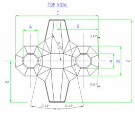
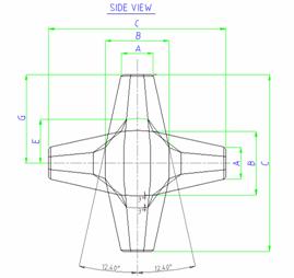
In these figures the dimensions are related to the height of the unit, C, as follows:
A = 0.179 C
B = 0.360 C
D = 0.640 C
E = 0.248 C
F = 0.175 C
G = 0.500 C
J = 0.320 C
The Core-loc placing pattern is illustrated in the 3-D figure below. This view shows the placing grid with a centre to centre placing dimension of “x” (this dimension can be calculated with on the “Core-loc Design” page). Core-locs are shown scaled down to illustrate the pattern of rows and columns clearly. Note that the first row (toe units) are placed on the same level as the second row. Where rock toe mounds are required (or preferred by the designer) the first row will not be required.
This view shows the same placement grid as above with Core-locs at their actual scale and different colours for alternate rows.
This is a side view of columns 1 and 2 with a typical rock underlayer and illustration of placing first and second row units at the same level. Foundation conditions need to be addressed for the toe design and a sacrificial rock toe mound is required if there is a risk of scour. If a properly designed rock toe mound is provided the first row of Core-locs will not be required.